
Box it Out: Quadimodo, Part 3
- Eldan Ben Haim
- Feb 10, 2022
- 9 min read

For this blog entry, allow me to start by expressing my appreciation for you taking the time off the daily Wordle quiz to come here :) With that out of the system, let’s get started.
Other than writing software and working on strange contraptions in my workshop, one of my favorite passtimes is playing the piano (or other keyboards). Much like my other hobbies, I don’t do it particularly well but it nevertheless has an important part in my overall well-being. Occasionally I would watch a YouTube video about some music-making gadget or another (a synthesizer, or a sequencer), and decide that I “need” that gadget. How easy it is to forget that the fine music produced in that YouTube video is not only attributed to the instrument but also to the talent of the person operating it… Luckily I’m painfully reminded of that truth shortly after the gear arrives!
My latest endeavor of this kind was purchasing the K.O Pocket Operator. Pocket Operators are a series of electronic musical instruments made by Teenage Engineering. There are various drum machines, synthesizers, and the K.O is essentially a lo-fi sampler. Each of the Pocket Operators comes built-in with a pattern sequencer, and they can all be synced into an electronic orchestra. Now, if you’re thinking about a keyboard-thingie with a 4 figure price tag when you read this then you’re waaaaay out. These are $49-$99 gadgets and what I really like about them is that they’re shipped as basically a bare-bones PCB with components soldered on it. Enclosures are for the weak. Don’t event get me started on push-button caps. Real performers use raw PCBs; in fact they solder them while on stage. And then code their microcontrollers in Assembly. Or something.
So obviously playing with a K.O Pocket Operator didn’t make me an any better musician. But it did make me think about how amazingly useful, and pretty — PCBs are. And how exciting it is that it’s possible for us Makers to plan a custom PCB and have it manufactured with low latency and at a low cost. Which brings us back to Quadimodo.
Going for a PCB
Indeed, after building a few motor control circuits based on MOSFETs, and then frying them or breaking them or otherwise rendering them unusable (see the previous part in this series for more details), it became evident that the weight of the prototype board with 4 MOSFETs and capacitors was a little too much for the weak motors I used. While the quad was perfectly able to balance itself on the table (yay!), it would not really be able to lift itself to a substantial degree (boo!). And so, based on others’ learnings, I’ve decided to order a custom made PCB for the control circuitry — and one that will be based on SMD components so that they’ll be small and light. While at it I also went on MOSFETs that were a little more optimal in their electrical characteristics for controlling Quadimodo’s motors.
I’ve already previously ordered a custom PCB from JLCPCB for another project, however that was only a through-hole PCB without any assembled components. This time, I was going to order a PCB with some assembled SMD components — capacitors and MOSFETs mostly. So I fired up KiCad, which is an amazing free CAD tool for PCB design. I’ve prepared the schema for a PCB that would include:
The 4 motor drivers (MOSFETs with supporting circuitry),
A connector for the 6-DOF IMU,
A header connector for connecting a WeMos,
Supporting circuitry for receiving external regulator power (5v)
I’ve also thrown in another circuit segment, “enabled” using a solder-jumper, that would allow feeding power to Quadimodo from a Li-Po battery through a voltage regulator. I’ve added this segment as a shot-in-the dark: first, I didn’t really care to power Quadimodo using a battery (at least I didn’t think I cared, see below). Second, since I didn’t use fly-back diodes, based on what I read I assumed that it’s very plausible that the voltage regulator will be fried by back-current from the motors — as I saw happening with some of the WeMos D1 mini boards I fried in earlier prototypes. So I was going to have this as a first attempt in case I did want to pursue battery-power.
The workflow for designing and manufacturing a custom PCB with KiCad starts with drawing a schemata for the PCB. You can see Quadimodo’s schemata below (this version does include fly-back diodes for the motors).

The next step is drawing the boundaries of a PCB and then laying out the components. Like many other PCB CADs, KiCad would prepare the footprints for the different components and will guide you through the connections that need to be made, but it’s up to you to actually layout those components and route connections between them. Specifically with Quadimodo this also required paying special attention to the fact that some of the traces (the “connections” on the PCB) needed to be particularly wide to carry high current through the motors. After a few hours of work I had a completed board layout:

Ain't this really pretty? Once the PCB layout is complete, the final step is to export a set of files form KiCad that are then provided to the PCB manufacturer (JLCPCB in my case). These are files that describe the board itself as well as files that list the components that need to be assembled and where they should be placed. I guess the process of exporting these files and preparing them for consumption by JLCPCB could be easier than it was (e.g JLCPCB could be perhaps more tolerant to the formats of files that it is happy to consume, and specifically not make a fuss around KiCad exported files).
Nevertheless, this was not quite rocket science — allowing even an amateur as myself to complete the entire thing probably in less than 10 hours of work. Sure enough, after two weeks and less than $20, I have received 5 units of assembled Quadimodo controller PCBs:

Note the following in the PCB above:
Connections to the four motors on the four edges of the PCB (J5, J3, J4, J6).
Holes for soldering 2 power supply caps (C3, C1) and diode (D1).
Holes for soldering header connections for the WeMos D1 Mini (see two row of holes roughly at the top and bottom of the middle third of the PCB)
Holes for soldering connection for the 6-DOF IMU (perpendicular to the top WeMos D1 Mini header)
Jumpers for connecting a battery or direct DC power supply to the board (J1, J7) and a couple of solder jumpers (JP1, JP2) for enabling the battery-based circuitry.
A New Chassis
Now what’s left is solder the missing components and mount it on.. err.. Hmpf. Obviously the old chassis wouldn’t carry the now bigger PCB. So back to the drawing board, planning a new chassis and printing it. Since I had to design and print a new chassis, I might as well add some more improvements to it… And indeed I’ve done the following:
Longer “arms” again, allowing for yet bigger propellers.
The longer arms are built of two sides rather than a single arm; this is lighter and more sturdy.
The motor holders: previously I used duct tape to hold the motors inside a “well” that was slightly larger than them. This was obviously not ideal in terms of rotation etc., and I’ve lost quite a few sets of motors due to the fact that they would vibrate in place and sometimes rotate in place to the point their wires would tear up. So this new chassis was built with motor holders that were smaller in radius than the motors but included a notch that allowed me to pry them open, insert the motor and they would then keep it in place. I’ve also designed these motor holders to fit a geared motor kit, as I wanted to experiment whether these kits were more powerful. I ended up passing on this test.
The new chassis, with the PCB constructed and mounted on it, can be seen here:

Of course I had to rework the PID coefficients to teach this new beast to stabilize itself on pitch and roll. Once that was done, I was finally compelled to try letting it stabilize itself in mid air:
See that content look on my face? Nothing like small successes.
Quadimote
It was time to graduate from on-the-bench experiments to more demanding flying conditions, like, um, actually flying. However, I needed a better way to control the drone before I let it out of the table mount. That was a great opportunity to turn to less frustrating, smoother activities in the project — specifically, making some software :)
The plan was to code a remote control that would run on my iPhone. Aptly named Quadimote, the app would present controls on screen and send UDP packets in the same protocol the desktop control station did. I’ve decided to take this opportunity to write in SwiftUI (didn’t do SwiftUI before), which led to some exploration of SwiftUI internals (obviously crucial for building a simple remote control program) — a subject for a different post. I actually started coding this on my iPad Pro, in Swift Playgrounds. It was fun to finally put this device to use for some “development” work. The result was something similar to this simple UI:
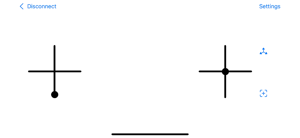
Note the minimalistic apple-like design (read: my graphic design capabilities end at drawing intersecting black lines). The left control is for throttle and yaw; you use touch to move the “knob” (the circle…); when you take your hand off it goes back to the position in the picture. The right control is for roll and pitch. Here you can either use touch or by clicking the top right button (the one with the three axes) you can activate motion control — so you tilt the phone to control roll and pitch. Clever. I wish I could claim credit for it but this was actually inspired by a drone I got for my son (thanks for the vote of confidence, son!), with similar tilt-based control using a “watch” you wear on your arm. Finally the bottom right button is to instruct the drone to recalibrate itself.
Clicking on the “Settings” in the top right of the screen takes you to a series of PID settings pages:

Obviously there's support for controlling multiple quads, and you can save PID profiles for each of them separately. Guess I got a little carried away there.
Doing the Wright Thing
With the remote ready (or at least an early version of it), there was no longer an excuse to postpone a real flight experiment. Unsurprisingly the first attempts weren’t very successful:
Soon it became quite evident that I had too many strings attached ;). Remember that the PCB was designed to include a battery-drive circuit, which I assumed won’t work well. I was planning to revise the circuit and order a new one, but decided go give the current design a shot. And what-do-you-know, the gods of passive components were smiling at me (I guess the could no longer stand seeing my suffering) — the thing just worked on batteries.
Well, at least for some value of “worked”. It would take off, and remain stable for a few seconds, then start destabilizing (mostly on the yaw axis) and crash.
What followed was a series of frustrating, failed attempts to make the drone fly and stabilize itself especially in the yaw axis. This was a low point in this project and I was at times very close to letting go of this, nullifying all the work I put into it in the more than the last year. Hours of PID calibrations, replacing pretty much every mechanical part of the drone -- all to no avail.
The last modification I made finally got the drone to work (obviously, that's why it was last). I’m not entirely sure why, but here’s how the story goes: these coreless motors that I bought come in two versions — one for clockwise rotation and one for counter-clockwise rotation. Generally speaking if you want to reverse a motor’s rotation direction, you reverse the polarity of the voltage you supply to it. So I was somewhat puzzled by why there were two separate versions for the different directions. I’ve read somewhere that this relates to the geometry of the brushes which helps to decrease motor wear when spinning on the designated direction. Since I didn’t care about earthly matters such as wear and longevity, I basically used whatever motors I wanted and hooked them with the polarity I needed.
As I was fighting yaw stabilization (or rather lack thereof) I tried replacing motors one by one, and measuring whether I can generate yaw-rotation in both directions by simply maxing one pair of motors and turning off the other pair completely. In order to achieve that I constructed a rotating-table (a piece of wood glued to… a.. spinner. Wait till you hear about my clean-room), mounted the drone to it and just turn on one pair of diagonal motors at a time (and then one single motor at a time). This was done again using the desktop control software which allowed manual controls of the motors.
It soon became clear that Quadimodo consistently had trouble to generate yaw rotation in one direction. So I went ahead and replaced the motors once again, and when that didn’t help I decided to replace the motors again but this time without ignoring the designated rotation direction of each motor. That, embarrassingly, worked. Given that these were all el-cheapo motors from Ali Express, and from different suppliers, I can’t really tell if they were just better motors or the designated direction thing has a more significant effect than just motor wear. If the problem was indeed the rotation direction/, I guess I'm proud to report a 21st century reproduction of the incident that gave birth to Murphy's law.
Bottom line: it flies.
Epilogue
And thus, this journey came to its end. Happily, with 1 working quadcopter, a remote control app for iOS, an unreasonable amount of spare coreless motors, propellers, PCBs, lots of newly acquired knowledge and a couple of open questions.
The code, mechanics and electronic designs are all available in my GitHub repository.
Quadimodo is now packed in the “finished projects” box (which is getting full!). Perhaps in a year or two I’ll revisit it for an enhanced version (e.g add the fly-back diodes, fix the orientation computation code), but for now I’m content.
Comments