
An Electronic Teaching Chess Board
- Eldan Ben Haim
- Jul 19, 2022
- 18 min read

A few years ago, one of my kids started to develop interest in chess. He started taking lessons, and playing the game with the rest of the family at home. When he was playing with his siblings, who had more-or-less the same level of expertise as himself at the time, the games were somewhat amusing to watch. Pieces of both sides would travel on the board in a graceful dance — albeit not following the original game rules. At times a “Check” state would remain unannounced for several turns, and there was at least one time where the two players continued playing after an unobserved Checkmate.
When playing with one of the adults games tended to be more… compliant. And still, I was never a good chess player myself; I find that I’m unable to concentrate in analyzing the board. Often I make moves that directly cost me a piece — where if only I’d methodically scan the board it would be obvious I should avoid those moves. So all in all I would say that I wasn’t that much of a tutor, and the boy is lucky that his Chess studies were outsourced to a third party.
Realizing how difficult it can be for young, new players to keep all game rules I figured that building a chessboard that will assist in gameplay can make a really nice project — And thus I’ve set out to work on that.
The Plan
The plan was, then, to build a chess-board that would be aware of the piece arrangement, and will provide assistance with rule-keeping to young players. While I’m at it, it would be grand if the board could prevent me (or any other player) from making my infamous stupid chess mistakes. This overall story quickly became an itemized list of more concrete requirements; not all of these were completed as part of this project.
Setup:
Assist players in setting up the board for a new game.
Allow players to start from an arbitrary game configuration.
Allow players to “save” and “restore” a board configuration. [Was never started]
Gameplay:
Assist a player in making valid moves:
Indicate to the players which pieces they’re allowed to move — taking into account all game rules, and Check configurations
When moving a piece, indicate to the player where that piece can move to, taking into account all game rules (e.g disallow exposing the king to a Checkmate).
Detect check and checkmate configurations, and alert users to them.
When moving a piece, mark “stupid moves” — e.g moves where a piece is exposed to an immediate attack.
Support promotion, castling, etc.
Other:
Players should not be required for any significant effort or attention in order to benefit from the above assistance functionality
Allow players to opt in and out from the various types of assistance
Support projecting board configuration on a screen / computer [Was not completed]
Allow chess games to be played on two remote boards [Was not completed]
Teach players about known chess openings [Was never started]
Allow a human vs. computer game [Was never started]
Now, of particular importance is the requirement that the players shouldn’t exercise effort or attention beyond playing the game. First, this implies that the players shouldn’t need to manually input or update their moves beyond executing them by physically moving game pieces. Second, we need some display system that would allow providing information such as “here are all the moves that you can make” in a clear, intuitive way that won't distract the players from the game too much.
For move input I opted for using magnetic pieces and reed switches. A reed switch is a switch that consists of two thin metal foils placed in a glass capsule maintaining vacuum. When the switch is placed in a magnetic field (or in our case a magnetic field is ‘placed’ near the switch), the metal foils make contact and the switch is “closed”.

By placing a reed switch under each board schedule we can tell if there’s a piece there or not. And, if we assume players don’t game the system (heh), given an initial board configuration we can track the ongoing game. For example, suppose we start with an initial board configuration. We’re expecting to see all switches in rows 1, 2, 7, 8 closed. Now if we see switch D7 open, we know that a pawn is lifted. Next if we see switch D5 close we know that’s where the pawn was placed (so this was a D7->D5 move). If instead we see switch E5 close then we’re encountering an invalid move — and we should somehow alert the user and help them re-order the board. This may get a little more complicated for some moves: eg., when capturing or castling. When capturing, this system does require the player some more attention than usual: the player is expected to first left the capturing piece (just like in any other move), then lift the captured piece and then place the capturing piece in place of the captured piece. This is not an unnatural way to play, but players need to make sure that adhere to this order of events. Of course, if they don’t the system needs to somehow alert them.
Which brings us to how we provide feedback to the players. Obviously we need to have a display that would allow us to present messages and guide the player throughout the game. But a lot of what we want to inform to the player revolves around pieces and their placement (which pieces they’re allowed to pickup, where they’re allowed to place them, where it would be risky to land, etc.) We can, of course, present the schedule coordinate (‘A3’) on the screen; and in fact we probably should. But I didn’t want the player to have to resolve coordinate through the entire game, hence I decided to provide feedback by somehow illuminating relevant schedules on the board. I ended up not illuminating the entire schedule, rather including a two-colored LED lamp at the corner of each schedule (below the board) and a transparent “hatch” that lets that light through.
Humble Beginnings
A chessboard has 8x8=64 schedules, and for each schedule I would need to have a two-colored LED and a reed-switch mounted. This is 64x3=192 mounted parts, which calls for some non-trivial mounting mechanics (mechanics is never trivial for me). I would have to experiment with several designs, and every good developer knows that sometimes the difference between an OK result and a great result is having a solid REPL to experiment with. Since I was using OpenSCad at the time (and later during the project switched to openjscad), it was not problem to design a parametric piece, manufacture it for a 2x2 board, evaluate it, rinse and repeat until we get a satisfactory design — and then manufacture the piece for an 8x8 board. And indeed, here’s a video of one of the prototypes in its 2x2 version, along with a rendering of the full 8x8 board.

As you can see above, the plan at this point was to have a full-board chassis, with printed and cut schedules on top of it, and the LEDs and reed-switches mounted on it beneath the printed schedules.
With this satisfactory prototype, I’ve set to start working on the hardware.
Input and Output Matrices
With 192 input/output components (LEDs and reed switches), we would naively need 192 input/output pins — hardly a reasonable count. So we turn to an old trick — using component matrices for input and output.
Let’s start with the LEDs. An LED has an Anode and a Cathode. For the LED to emit light, the Cathode needs to be connected to GND and the Anode needs to be connected to a driving voltage. Trivially, both should apply for the LED work. Now consider a single LED, where we connect both the Anode and the Cathode to separate microcontroller-controlled source and sinks. There’s exactly one I/O configuration in which this LED will light — both source and sink active. Success! We’ve just controlled a single LED with two I/O ports ;) Actually, this method only gets interesting beyond 4 LEDs: let’s imagine a 3x3 matrix of LEDs (see diagram below). Connect all LEDs in the same row to a single micro-controlled source (so we have 3 micro-controlled sources) and all LEDs in the same column to the same micro-controlled sink (so we have 3 micro-controlled sinks). Each of the 9 LEDs now has its own unique combination of source + sink that need to be active in order for the LED to light up. So, we can light any single LED out of 9 LEDs using 3 + 3 = 6 I/O pins. For 64 LEDs we can use 8 rows + 8 columns = 16 I/O pins. Definitely better than the naive 64. And for 128 LEDs we could use 11 rows + 11 columns = 22 I/O ports. We can, of course, use other suboptimal configurations. In our case we have 64 two-color LEDs so we’ll use 8 rows + 16 “columns” (8 for each color) = 24 I/O ports.
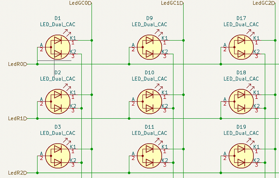
Now, with this method we can’t really make any pattern of LEDs work. For example, suppose we want a diagonal of LEDs to light (Row 1, Column 1; Row 2, Column 2). To light up the first LED, we activate the source for row 1 and the sink for column 1. To light up the second LED, we active the source for row2 and the sink for column 2. All in all we activated two sources and two sinks. But this means that the 4 top-left LEDs will light: these are the 4 LEDs that correspond to (source 1 or 2, sink 1 or 2).
So how do we light up a “diagonal” of LEDs? We exploit “Persistence of Vision”: The same principle behind how we see movies and, really, most displays around us. Thanks to persistence of vision, we don’t really need all LEDs on the diagonal to be constantly “on” to create an illusion that they are. If the LEDs blink fast enough, we’ll create an illusion of them being constantly on. So we can sequentially turn on each of the diagonal LEDs for a short period of time and create this illusion. Obviously this works for any pattern of lights: we can sequentially, repeatedly light the desired LEDs for short periods of time and keep the others turned off. This process is sometimes referred to as “scanning”. The time between subsequent “scans” is often referred to as “refresh period”. The period of time each LED will be on for is (refresh_period / num_of_lighting_leds), and each LED will be on once every refresh_period. If refresh_period is too high this means that LEDs are blinking too slowly and we’re losing the Persistence of Vision effect. So we need to keep this number low — which means that we need to scan as fast as possible.
The duty cycle of each LED (the portion of time that it is lit) is, based on the formula above, 1/num_of_lighting_leds. And here lies a problem. Intuitively, the duty cycle determines how bright we perceive the LED is lit. Given our calculation, the brightness of the displayed pattern depends on the number of lighting LEDs it includes; hardly a desired property. This is why we alter our formulation of scanning such that we iterate through all LEDs whether they should be lit or not in the pattern, and either light them or not. Now, from a timing perspective — the period of time for each lit LED to be actually “on” is refresh_period / total_num_of_leds, and the duty cycle is 1 / total_num_of_leds. So we have a constant duty cycle, independent of the scanned pattern. Yey!
… but can we do better? For 128 LEDs, the duty cycle for each LED is going to be 1/128. Which is not very high. They will appear very dimmed. Luckily we can improve on that. Recall that we’re scanning because we can’t generate any arbitrary pattern of lights across the entire matrix. However if we consider a single row of the matrix, we have LEDs connected to a single source and individual sinks. This means that we can generate any pattern of lights we desire at once in a single row. So we can now “scan by rows” — turn a single row each scan, but update all columns for that row at once (or rather — first update the columns and only then turn on the row). With this setup the duty cycle for each LED is actually 1/num_of_rows, or in our case for 128 LEDs it’s 1/8 — 16 times higher than our previous approach!
To sum up where we are right now, we have devised a plan to display an arbitrary pattern on 64 two-colored LEDs with a 1/8 duty cycle and using 24 I/O pins.
Well, 24 I/O pins are definitely better than the 128 started with, but can we do better? It turns out that we can :) By using shift registers, we can further reduce the pin-count. A shift register is a logic component with a clock pin, a data input pin, and a number of data output pins. Whenever the clock is triggered, the values in the output pins are shifted (so the previous value in output pin 0 is loaded to output pin 1, the previous value in output pin 1 is loaded to output pin 2, …), and the data from the input pin is loaded to pin 0. For example, consider a 5-output shift register. If we trigger the clock with a sequence of “high, high, low, low, high”, the first 5 output pins will be “high, high, low, low, high”. Another trigger with “low” will change the output to “high, low, low, high, low”. Here’s a small animation to depict this (taken from here):

Shift registers often have additional functional pins. For example, they often come with a “latch” pin which means that you can shift bits into an internal state register, and only when you’re done shifting you trigger the latch pin to load this internal state register into the output pins. This means that you can atomically change the value of the output pins. Also in many cases shift registers include pins that allow them to be daisy-chained; using these pins we can take two 8-bit shift registers and construct a 16-bit shift register from them. Back to our goal, we can construct a 16-bit shift register and thus replace 16 of the 24 I/O pins with only 3 (clock, data in and latch). And similarly we can use 3 additional pins for an 8-bit shift register for the rows. So instead of 24 I/O pins we can use 6. …but can we do better…? It turns out we can, but we’ll get to this later.
In the chess board circuit, I used the 74HC595 IC for all 3 shift registers. The shift registers’ outputs are connected to driving ICs — these are ICs that are designed to either source or sink a relatively big current. For source I used UDN2981 and for sink I've directly used the 74HC595 IC (which also means that the bits it outputs should be inverted for a LED to light up).
Now that we’re done with outputs, let’s cover inputs. We need 64 reed-switches, us-from-several-paragraphs-ago would think this means 64 input pins. But we’ve grown smart since then! Perhaps we can put some of the same techniques we discussed for the LED display into use here? First consider that we don’t really need to know all the time the state of all inputs. It’s enough if we’re able to sample them at a reasonably fast rate (that’s, by the way, what your computer keyboard does!) We also know that with a 64-bit shift register (built from 4 daisy-chained registers), we can deliver power to one end of any single switch out of the 64 switches using a mere 3 I/O pins. Then we can sample the other side of all switches with another single I/O pin — we call that the sampling pin. Our scanning routine is: power up one of the 64 switches by manipulating the shift register; then sample the sampling pin to understand whether the powered switch is closed or open.
Again, from a duty-cycle perspective things are sub-optimal. with a 1/64 duty cycle it means we’re going to have to sample really quick for input to be responsive. Can we sample multiple keys at once? Yes we can! Again let’s connect each row of switches to the same power “source”, and each column to its own sampling pin. Scanning now involves powering up each row in its turn, and then checking which of the sampling pins are on. This samples which switches in the row are open and which are closed, and the duty cycle is 1/8. Easy Peasy. Well, unless you consider the fact that more than one switch may be closed — a common case in any chess game with more than one piece on the board :)
The problem with multiple on switches is that they can generate “ghost” pieces with the row-scanning approach. Consider the following switches are “closed” (on): a := Row 1, Column 1; b := Row 2, Column 1, c := Row 2, Column 2. We’re now scanning Row 1, so switch a is “powered”. This means that the lead from switch a that’s connected to Column 1 is powered. Switch b however has one lead connected to Column 1, so current flows there… to the lead connected to Row 2. Which means that switch c is powered as well, and since it’s connected to Column 2 — Column 2 is powered. So our scan, when powering Row 1, will see voltage in Column 2 — and conclude that the switch in Row 1, Column 2 is closed despite the fact that it isn’t.

We can fix this by adding Diodes in series to each of the Reed switches:

The sources for the switch rows, along with their controlling shift register, can actually be shared with the sources for the LEDs. So we actually only need an additional 8 input pins as the sampling pins on top of what we already have.
As you may have guessed, we can do better. A parallel-in, serial-out shift register is kinda the inverse of the shift registers we discussed so far. The parallel-in, serial-out shift register has several data inputs, a load pin, and a clock pin and a data-output pin. Using the load pin we ask the chip to sample the current input in the 8 data inputs, and present the first of the data inputs in the data-output pin. We can then trigger the clock pin to present subsequent bits in the data-output pin. Overall with 3 pins we can sample a number of input pins — in our case, 8 of them. For the chess board, I’m using 74HC165 for the parallel-in, serial-out shift register.
Other Hardware
In addition to the reed switch and LED arrays, I wanted the chess board to have a small keypad and screen. I went for an OLED display and 6 tactile switches (4 arrows, confirm and cancel). The OLED display is connected through an I2C bus, and the keypad can be thought of as an extra row in the reed array matrix. For practical reasons, the keypad’s source was its own dedicated micro-controller rather than another shift register IC, but it did share the same parallel-input shift register with the reed switch array. Also there were no diodes involved here.
For a microcontroller I chose the ESP-32 for this project; since eventually I’d like it to play chess, which involves running some long algorithms for higher player levels, I wanted something that was faster than my usual preference of ESP-8266 or an Arduino board.
The diagrams below summarize the entire circuit, without the detailed switch and let matrices.

How Not To Build An LED Matrix, And How To Build One
Diagrams are easily drawn. Circuits often prove to be more challenging to build ;) Especially a 16x8 LED matrix. My original naive course of action was to have 16 + 8 insulated wires, remove their insulation in even spaces and then solder the LED connectors to the wires where the insulation was removed. Removing 192 bits of insulation from 24 wires certainly was a stress test for my determination — but doing this in our kitchen, next to family over 2 or 3 afternoons definitely helped.
Soldering the LEDs was much more complex. I ended up creating a cardboard template where I mounted the LEDs, and then soldered the wires to them. Of course once in a while a connection would get de-soldered, or a short-circuit would occur; but after a while I developed a “system” and soldering went pretty smooth from there.


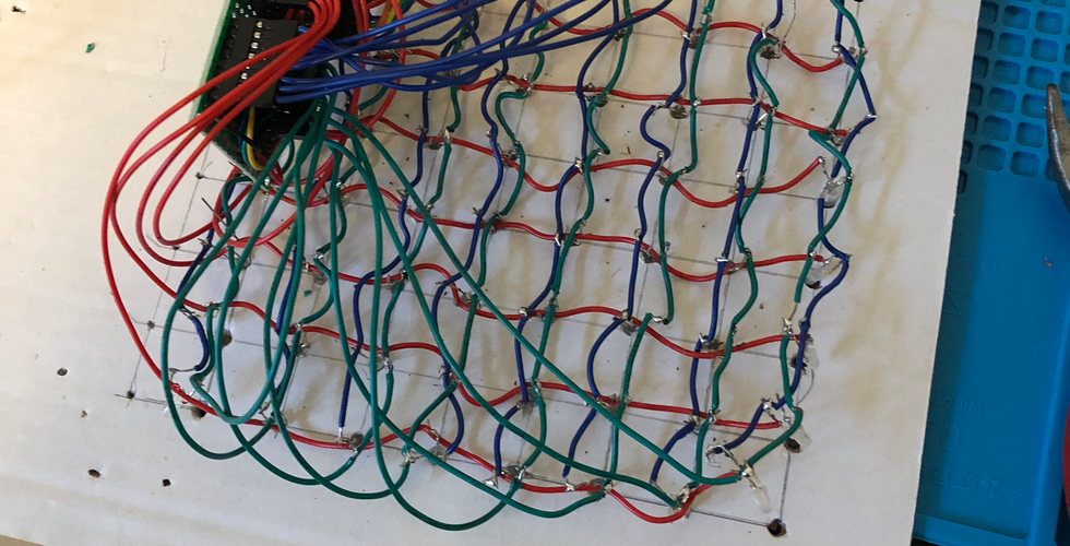
I finally had a working, hand-soldered LED matrix which I could now mount on the chassis that I’ve printed. Which is where I realized I was all wrong. In the beginning, the LEDs would hardly fit into the skeleton. Then they weren’t snug enough. I tried to glue them but they would occasionally fall off.
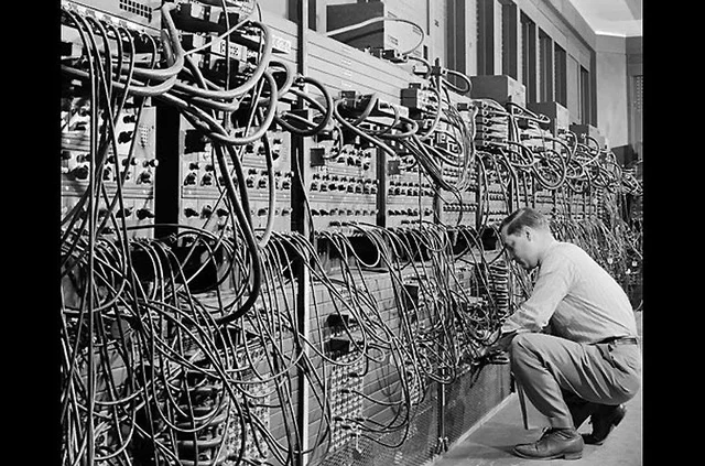
And, every once in a while one of the connections would disconnect and I needed to re-solder it. Finally, in a moment of being honest with myself I realized that this array of wires isn’t going to do good to anyone, definitely not with the additional wires I was going to add for the reed-switch array… it would quickly become one of those massive bulks of wires that you some time see in photos with a caption that suggests that somewhere in there there’s actually a computer from the ‘40s.
It was time to back-track after all that manual labour, and rethink how to construct this chess-board project. After much deliberation, I decided that anything that would be remotely close to the amount of effort that I’ve put into repetitive manufacturing tasks will simply make the project uninteresting for me. This was a good call since it eliminated several alternatives for moving forward. In fact, it pretty much singled out one solution: manufacture a PCB. At the time I’ve been fiddling with the idea of manufacturing PCBs at home, eyeing laser printers that would be suitable for creating toner masks for transfer to copper boards etc. I even bought the chemicals and boards, but haven’t got to actually trying this. However, given the frustration that this project entailed so far, I wasn’t sure that this was going to be a fun attempt. But then I remembered that I’ve heard about those PCB-prototyping services where you send a PCB plan and get the PCB manufactured for relatively cheap. One such service is JLCPCB — and after a quick search I decided to try out their service for this project. I would have to somehow create a plan of the PCB. I’ve never used an EDA tool before; this was quickly becoming exciting! After looking at some options, I went for the free and mature KiCad. In fact, it was only when I started using KiCad that I had the circuit diagrams above made.
Editing my first PCB proved to be more difficult than I had anticipated. Routing connections in a matrix, through IC connectors, when you’re skeptical about manufacturing tolerance (so leaving a lot of “safety” space between wires and connectors) was somewhat tedious — though nowhere close to manually soldering the wires… I’ve learned quite a bit about PCB construction and surely made every possible mistake along the way.
With a PCB, I no longer needed a full solid chassis for the board. Instead I designed a grid that would hold the printed schedules just above the LEDs, and a control panel to mount the display and keypad. Also I printed 4 plastic “feet” on which the board would stand (with a cavity for a bolt that would mount the feet on the board). Of course this was planned when I designed the PCB, to include the necessary mounting holes in it.
Since I already had most of the components I needed for the chess-board in stock, I went for a PCB-only option, without components. When I finished planning the board, I exported the plan and uploaded it to JLCPCB. The export/upload process seemed a little more complex than necessary, but not something that can’t be done with some manual editing. I have since ordered a couple of boards for other projects and the situation has improved vastly. The chessboard PCB had a bigger footprint than what’s typically offered by those PCB prototyping services in their cheapest price tier, but still the overall price (for 5 boards!) was, if I remember correctly, well below $100. The photos below show the PCB with some components soldered, and then with the rest of the mechanics mounted. I give you, in all its glory, the Model-N:


Software
The software for the chess-board consists of 3 layers. The first layer is a “hardware abstraction layer”. This is what implements the basic functions for controlling the hardware. Operations such as “blink red LED at A3” or “is there a piece on B2?”, “is any keypad button pressed?” and “draw text on the OLED display”. Much of this code is dealing with the shift registers mentioned earlier to implement the “scan” loops for input and output. Normally one would implement such scan-loops using timers and interrupts, but I found that for this project since I had a run loop (see below) doing a scan on each loop iteration was a simple enough solution.
The second layer is an event-driven UI framework. This is based on bits of codes that I written over the years for implementing event-drive UIs on Arduino-class boards. We have an event loop which basically reads events from an events queue and dispatches them to a “current UI state” in a state-machine. We have event sources that poll or otherwise generate events and place them in the queue. An event source may be, for example, a timer, or the HAL discovering that a button was pressed or a piece was placed or removed. When a state receives an event it may request the framework to switch to a different state. Some states are general-purpose UI states, such as showing a menu on the OLED screen and allowing the user to make a selection, displaying an on-screen keyboard and waiting for input, or showing a form with multiple controls. Other states are more application-specific; for example in our case, we have a state for waiting for a player to pick up a piece, a state for waiting for them to remove a piece, etc. This mini UI framework has served me well across several projects by now, and perhaps some day I’ll factor it out as a standalone library.
A simplified state machine for the chess game is drawn below; some trivial transitions are not included but I’m sure you get the gist of things. Of particular interest is the “Board Review” state, which is generally invoked whenever there is delta between the expected state of the board and the detected state (e.g when the board detects a piece on a schedule that’s supposed to be empty). In this mode, the board will instruct the player (using the screen) first to remove pieces from schedules where pieces are detected and that are supposed to be blank. Then, as long as there are schedules where pieces should be present and there are missing pieces, the player will be instructed to place the proper piece in the proper schedule. The player can then confirm the board is setup appropriately. Note that the process is much less painful than it sounds since typically there will not be more than 1-2 schedules to fix.

The Board Review step is also invoked when castling is made (this makes the move less confusing) and on game start — to set up the board.
The last layer is, of course, the application layer. This consists of the “chess business logic” code, as well as the application-specific UI components to drive the game. The chess business logic include the code for representing board configurations, checking move validity, identifying check and checkmate situations, enumerating moves, etc. As you can imagine, writing this code involves quite a bit of testing and experimentation which — that’s right — calls for a tight REPL. This was implemented in the form of a Mac desktop app that included the platform-portable set of classes that make the chess business logic layer, and allows simulating a chess game on screen. This allows interactive experimentation. I have, alas, not generated unit tests for this code; an interesting way to do that would be to use the interactive application to draw configuration test cases and record the expected results. Perhaps some day when I get back to a “version 2” with the features that I didn’t implement from the list above…
Epilogue
As always, you can find the mechanics, code and EDA files on GitHub. The repository most digital materials that you need to create a teaching chess-board yourself. To get you more interested, here’s a short video of how the board actually functions, featuring my kids as players. Enjoy ;)


Comments