
And Then Reality Bites: Quadimodo, Part 2
- Eldan Ben Haim
- Nov 12, 2021
- 12 min read

(This is part 2 of a discussion of Quadimodo, my attempt at building a DIY Quadcopter. You can read the previous part here.)
Much like the Knapp model for relationships, or the Kübler-Ross model for grief, I have devised my own model for the emotional/psychological process I go through with my engineering projects. I’ve always wondered whether this is just weird me, or there’s really an intrinsic psychology of engineering projects — so I’m outlining the model here and would love to get your comments on it.
I call Stage 1 “the passionate stage”. This is where you’re haunted by this idea, characterized mostly by a vague goal or end-result, and a very high-level understanding of how to get there. The prospect of being able to solve an intellectually challenging problem, and the content that would follow, lure you into taking the plunge and committing to the project. For hobby projects, this stage is crucial — it’s what propels you from the TV chair to your desk after a busy day at work.
Stage 2 is “exploration”. Everything is still new, and you start fiddling with the problem space. Small early successes bring with them joy, and you’re building confidence in the ability to land the project. As you’re mapping out the challenges, putting together a plan and starting to work on them, you are bound to then reach…
Stage 3 — “disillusionment”. This is where reality bites. You’re done with the easy part of the problem and come to a familiar realization that things are not as simple as you initially thought. The world is not a simple linear model of variables. Motors generate noise, software has bugs, photographs are taken under varying lightning conditions, storage is finite, databases are slow, O(n^2) is a lot for big numbers, and a Compact Disc’s plane of rotation is not parallel to the pickup-apparatus tracking plane. In short, Real World is persistent in complicating Really Simple problems.
Stage 4 — "getting personal". This is where it becomes clear that your entire credentials as an engineer depend on the success of this specific project. If you don't solve this one, then any accomplishment that you may have had in the past 10 years is going to be undone and forgotten. A tough spot, but definitely a motivating one.
Stage 5 — “enlightenment”. You were able to solve some really tough problems as part of this project. You're now more confident in your ability to navigate through the problem domain. If you got here, you're likely to complete the project.
The previous post about Quadimodo took me through stages 1-3. It ended with a feature-complete but totally non-functioning apparatus; something you’d expect to find in Dr. Fred Edison’s lab. Indeed it was obvious that there was a lot to fix. And thus it became personal ;)
If you build it, it will fly
With the initial Quadimodo iteration, multimeter readings showed roughly 500mA were drawn by the motors at full throttle. Connecting a single motor directly to a power supply indicated that this is much lower than what the motors can draw. My choice of the ULN2803 chip was an immediate suspect (it has a relatively low current rating), so I ordered some through-hole MOSFETs from AliExpress and used them to switch power to the motors. I’ve soldered 4 MOSFETs and some resistors on a matrix PCB, and connected the motors through jumper connectors to this board. This new switching circuit allowed the motors to draw significantly more current (around 5A, probably limited by the power supply) and indeed it seemed that they were able to generate some lift. When powering on the motors the quad would hover, right before it would graciously flip and crash into the table. Still, the thrust seemed too low. Since I pretty much exhausted my switching options with the MOSFETs (in fact I was close to the current limit for my power supply) I decided to re-work some of the mechanics. I started with a frame that had longer arms. Such a frame would be better for two reasons:
Longer arms mean that I can install bigger propellers, and
With longer arms each of the rotors will generate more torque (around roll and pitch) when trying to control drone orientation.
I’ve also replaced the motors to ones that were slightly bigger. Now I really had a drone that seemed to be able to gain significant altitude (of course, at this point in time it was hard to tell because the drone had an understandable tendency to flip and/or crash soon after it’s started). The video below shows me letting the drone run while preventing it from going too high, flipping and crashing.
Missing from the video are the countless bruises that I got from the quadcopter flipping on me. Those propeller blades spinning in high RPM are not something that’s very fun to make contact with, but hey — I ain’t complaining. Let’s just say that throughout work on this project, friends around me would occasionally wonder if I had a new pet ;) Clearly, it was now time to start working on actually teaching the drone how to balance itself.
A Balancing Act
To balance the drone I would need to program the ESP8266 microcontroller to try keep the pitch and roll angles (remember those?) close to zero as long as we don’t want Quadimodo to move in the horizontal plane. Generalizing this in order to also support moving the drone horizontally, we want to be able to set a desired pitch and roll angles, and make the drone maintain those angles over time (and of course reach these angles if it’s not there when they were set).
Recall that in the previous post on this series we covered the basic dynamics of a quadcopter. So by now we know that there are pairs of motors that we need to throttle up or down depending on the desired roll or pitch motion. However, while we have the ability to predict the trend of throttling different motors, it’s hard to accurately predict the quantities. To illustrate, by going to a PWM duty cycle of 70% in the front- and rear-left (FL, RL) motors, and a PWM duty cycle of 80% in the front- and rear-right (FR, RR) motors, we know that the quad will have a roll angle to the left but it’s hard to tell what that angle would be. Contemporary engineering and physics may allow us to build a physical model of the dynamics, transforming PWM duty cycles to thrust, and thrust to roll or pitch angles. But there are many imperfections in the real, non-ideal quadcopter (some of them are even not my fault! ;)) that would render such modeling incorrect. For example, motor behavior is not consistent along the entire range of PWM duty cycle values. And quadcopter mass is not uniformly distributed, so its center of gravity is not in the middle of it. The different propellers are not really symmetrical in the thrust they generate, either AND they’re not completely perpendicular to the quadcopter plane (and not even parallel among themselves).
Consequently, we need to approach this from a different angle (heh). What we want to do is to program the microcontroller to make a best-guess adjustment to throttle values, empirically measure their effect on the quadcopter, and then make a best-guess correction according to the measured result. This process should, of course, be repeated until we reach the desired set-point (or we’re close enough based on our tolerance). Now, with our IMU and the sensor fusion code that we already wrote and discussed in the previous part, we have the “empirically measure” bit in place. But how do we go about making a good guess for how to adjust the throttle given our current measurement?
We turn to a control model called PID. PID stands for “proportional—integral—derivative”, which I must say is a bit of spoiler as far as names go. To explain it, let’s consider a Cruise Control system on a car, controlling the engine’s throttle to attempt to keep a set speed. We define a control “error” (denoted here as e(t)) as the difference between the desired speed and the vehicle’s current speed. A PID cruise control would compute the controller’s output value (throttle in our case) based on the current error, the current error’s derivative value, and the error’s integrated value. Each of these terms is multiplied by its own coefficient, and then they’re all added, to give this formula:
The proportional term basically ensures that if the car’s speed is too low, the throttle is opened, and vice versa. The derivative term is there to dampen the correction based on the rate of error change. This helps to prevent overshoot correction. Finally the integral term serves as controller “memory” — if there’s some “constant” bias that tries to bring the car out of its speed (e.g a slope) the integral term would eventually compensate for that. The control coefficients c1, c2 and c3 are usually manually calibrated in a PID system to obtain a desired tradeoff between speed of error correction, preventing under/overshoot and “length” of memory.
If we take this to back to Quadimodo, imagine we have a “knob” that affects roll. So, essentially the knob controls balance between the FL, RL motors and the FR, RR motors. E.g, when the knob is at 50% both pairs of motors have the same thrust. When it’s at 0% the FL, RL have higher thrust than the FR, RR motors and conversely when it’s at 100% the FR, RR motors have higher thrust than the FL, RL motors. If we denote the value of this knob (in the range [0,1]) as roll, and denote a base “throttle” value for all motors as throttle, we can say that the PWM duty cycle for each of the motors can be calculated as:
pwm_fl := throttle - (roll - 0.5) * max_roll
pwm_rl := throttle - (roll - 0.5) * max_roll
pwm_fr := throttle + (roll - 0.5) * max_roll
pwm_rr := throttle + (roll - 0.5) * max_roll
The coefficient max_roll above is used to set the maximum impact of the roll knob on our throttle value (we never want to really shut off completely one pair of motors). Try calculating the above PWM values for roll = 0, 0.5, 1 to get a feeling of how the roll knob changes the balance between the left and right pair of motors.
With this roll knob in place, we can run a PID controller to control its value. The output of the controller will be roll, and the error will be computed based on the sensor-fused reading of the quadcopter’s current roll value. We sample the IMU as often as we can, compute the quadcopter‘s current orientation and then compute its error relative to the desired roll angle. We can then numerically approximate the derivative of this error by dividing the difference of two subsequent error readings in the time that elapsed between readings. Finally by summing error values we can maintain an approximated integral of the error. Having computed the error’s concrete value, its derivative and integral over time we can now calculate a value for the roll knob and use that to compute the 4 PWM readings per the formula above.
Coding the PID control loop as described above is rather straightforward. Obviously this didn’t keep me from making some silly mistakes such as introducing rounding and integer truncation errors in several places. The main difficulty here was that detecting these errors was not always simple since it’s hard to tell whether erratic quadcopter behavior is due to a bug in the code, a physical limitation of the quadcopter or bad tuning of PID coefficients. This took a lot of patience and perseverance, but also tooling. After all, good tools are key to a job well done. Whether it’s scaffolds, screwdrivers, rotoscopes, multimeters, profilers, debuggers or a 3D-printed balancing table — time spent on tooling is usually a good investment.
For this part of the project I ended up creating three tools to help me getting things done. The first tool was implemented by extending Quadimodo’s network protocol and the Python control software to support setting PID coefficients from the desktop, and changing them “on the go” to help evaluate how coefficient changes are affecting quadcopter balance. This type of “command” later became the primary command used by Quadimodo’s remote control.
A second tool was a balancing table to which I mounted the quadcopter. The balancing table only (mostly) allowed the quadcopter to roll freely but not change its pitch or yaw. This allowed me to isolate tuning to balance roll without “noise” from other axis (yaw or pitch). I’ve prepared the table by 3D-printing two “surfaces” and connecting them with an “axis” made from an aluminum pole (taken from an old fussball table, later replaced by… a pencil).

A third tool was the ability to log sensor readings and control loop outputs from Quadimodo. This allowed me to trace how the control loop responded and identify, for example, some of the bugs I had around rounding errors and quantization in the PID implementation.
Creating these three tools took up a significant amount of time — but as always with tooling, it was worth it.
After several hours of tweaking, logging, fixing, getting bruised, increasing self doubt and frustration, finally Quadimodo was actually able to balance itself on the roll axis. You can see what this finally looked like in the video below.
Balancing on Two Axis
Now that Quadimodo was roll-balanced, it was time to consider pitch. The process is theoretically similar: we introduce another knob, pitch, and update our PWM formula as follows:
pwm_fl := throttle - (roll - 0.5) * max_roll - (pitch - 0.5) * max_pitch
pwm_rl := throttle - (roll - 0.5) * max_roll + (pitch - 0.5) * max_pitch
pwm_fr := throttle + (roll - 0.5) * max_roll - (pitch - 0.5) * max_pitch
pwm_rr := throttle + (roll - 0.5) * max_roll + (pitch - 0.5) * max_pitch
Now we introduce a second PID loop, that works exactly like the previous one, but this time it controls pitch and uses the pitch angle to compute the current error (obviously a good opportunity to create a “PID Controller” class that manages the PID loop and reusing it).
Good. Edit, compile, download to Quadimodo. Start by mounting the quadcopter on the same balance table (but rotated 90 degrees in the yaw axis) so we can teach to quadcopter to balance itself in the pitch axis independently from the roll axis. Works. Good day. Really.
So now all we need to do is to make sure the drone is able to balance itself in both axis. To do that, I’ve extended the balancing table such that it now had 3 parts: a base that’s fixed to the table, a mid-floor that can rotate in the roll axis relative to the base, and a top floor that can rotate in the pitch axis relative to the mid floor. So altogether the top part can rotate in both roll and pitch, but not yaw. Clever.
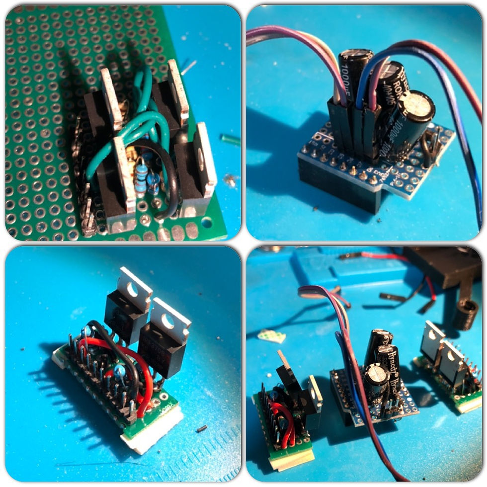
Mount Quadimodo to the table, start it, and ….. it won’t balance. Physics lifting its ugly head again. Some measurements and tracing of the control loop revealed that while the roll axis controller was working generally easy (meaning that once the drone was balanced the roll knob was typically kept within the center, so motor throttles were balanced), that was not true for the pitch knob. My suspicion was that this was due to the fact that all 4 MOSFETs were mounted on the same side of the quadcopter, making it really unbalanced w.r.t the pitch axis. So…. Back to the soldering station. I had to re-build to switching circuitry and split it into two pairs of MOSFETs, that I would place on two sides of the quadcopter.
Easier said than done. First, I had to build each of the two switching circuits (each housing two MOSFETs) a few times as I was becoming painfully aware to how sensitive MOSFETs are to static electricity. Somehow I got lucky with the previous build, but this time transistors kept malfunctioning. At some point I switched to using a gas-powered iron to make sure I don’t hurt the MOSFETs. Next, I suffered (well, the ESP8266 suffered, actually) from noise and fly-back current. Now, noise and fly-back is a fact of life with inductive loads and the sort of switching I was doing here. In fact, it was surprising that the in the previous build I didn’t experience these effects to a measurable level. Nevertheless, in this new build there was noise that kept sending the ESP8266 to reboot — and that was the good news. The bad news was that every few runs, I would basically burn an ESP8266 board. Most or all off them got their voltage regulator smoking at some point. In retrospect, I think this had to do with fly-back current from motors causing reverse current on the voltage regulators; some of these chips are particularly sensitive to such back current. The reason I’m concluding this is because when I added a diode that blocked such fly-back current (see below), no more ESP8266 boards were fried.
To handle noise, I did what many amateur electricians would do — I’ve added capacitors to reduce the noise and maintain proper current to the microcontroller board. Small caps across the motors, and then big caps across the power-supply to the microcontroller. Unfortunately the ESP8266 would still go medieval whenever the motors throttle was too high. Eventually I realized that fly-back voltage from the motors caused the big capacitors to discharge. When the motor current is disconnected (which happens quite a lot given our PWM drive) it would generate current in a direction reverse to the disconnected current due to the inductive nature of motors (inductors resist changes in current). Normally what you would do is connect a fly-back diode across the motor’s terminals. The fly-back diode allows the fly-back current to flow through it (effectively short circuiting the rest of the circuit and preventing fly-back current from reaching it), and will not allow current in the “wanted” direction to flow through it — so it will flow through the motors. Instead, I opted to just attach a diode that will prevent current flowing from the big capacitors to the motors — ensuring charge is available in the capacitor for the microcontroller. I’m pretty’s use that if this was a commercial / field-grade thing, I should connect the per-motor fly-back diode. But for now this works.
Between the experiments with capacitors, diodes and different layouts for the circuit (initially I had all 4 MOSFETs in the same side of the Quadcopter, and then I realized better to spread them to both sides to balance weight) I probably built 4 or 5 versions of the driver circuits, and burnt a similar number of ESP8266 boards. The photos below show some of these versions.
Eventually — I had a working Quadimodo that was able to balance itself in both roll and pitch axis concurrently (see video below). We’re getting close! Unfortunately, early experiments showed that now, with motors throttled for balancing the quadcopter, most of the time it didn’t generate enough thrust to lift… But more on this — in the next part.


Comments